Ammeter Circuit Diagrams: How to Read and Understand These Key Electrical Components
In the world of electrical wiring, an ammeter circuit diagram is one of the most important documents you can have on hand. This diagram shows how a particular electrical system is constructed, and it’s vital to understanding how electricity works within specific systems.
Whether you’re working with a household electrical system or a commercial-grade one, ammeter circuits are key components that must be understood and tested before anything else. Today, we’ll explain what ammeters do and how you can read an ammeter circuit diagram like an expert.
What Is an Ammeter?
An ammeter is an electronic device that measures current flow in an electrical system. It’s typically mounted directly to the circuit in question. A common type of ammeter measures the current using a coil with a magnetic core. This type of ammeter is called a moving coil type meter because its movement is responsible for measuring current.
Why Is an Ammeter Circuit Diagram Important?
Ammeter circuit diagrams are essential for understanding a particular electrical system. Not only that, but they’re also the first step in diagnosing any electrical issues within the system.
The purpose of an ammeter circuit diagram is to show how the various components of the electrical system are interconnected. This information can then be used to diagnose and fix problems within the system. Without this diagram, it’s impossible to accurately understand a particular system’s operation.
Reading an Ammeter Circuit Diagram
Reading an ammeter circuit diagram requires a basic understanding of electrical engineering principles. Before attempting to read a diagram, it’s important to understand some of the basic elements of an ammeter circuit diagram. These include:
• Power Sources: All ammeter circuit diagrams list the power sources used by the system. This includes both AC and DC power sources.
• Resistors: Resistors are devices that limit the amount of current flowing through a particular section of the circuit.
• Ammeters: Ammeters measure the current flow in a system. They’re usually placed at specific points in a circuit where the current needs to be monitored.
• Capacitors: Capacitors store electrical energy and can help to regulate the current flow in a system.
Once you understand these basics, you can begin to interpret the data provided in an ammeter circuit diagram. The diagram will show how each component connects to the others and how the current flows throughout the system. Usually, the diagram will include arrows indicating where the current flows, as well as labels identifying the components.
When reading an ammeter circuit diagram, it’s important to pay attention to the voltage and resistance values of each component. These values indicate how much current will flow through the system at any given time. By understanding these numbers, you can ensure that your system is running optimally and diagnose any problems that may arise.
Conclusion
An ammeter circuit diagram is a vital document for understanding a particular electrical system. By understanding the components of an ammeter circuit diagram, such as power sources, resistors, ammeters, and capacitors, you can ensure that your system is operating at peak efficiency. Take some time to become familiar with this type of diagram, and you’ll soon be able to diagnose any electrical issues in your system with ease.

Pico Ammeter Under Meters Circuits 12647 Next Gr

An Ammeter And A Rheostat Are Connected In Series Voltmeter Is Scientific Diagram

Ac Voltmeters And Ammeters Metering Circuits Electronics Textbook

Connecting Voltmeter And Ammeter Under Repository Circuits 31474 Next Gr

What Is A Circuit Diagram Draw The Labelled Of An Electric Comprising Cell Resistor Ammeter Voltmeter And Closed Switch Or Plug Key Which

Electronic Voltmeter Ammeter Circuit Using Single Ic 741 Under Repository Circuits 24855 Next Gr

Icl7107 Icl7106 Digital Led Ammeter Ampere Meter

Draw A Schematic Circuit Diagram Consisting Battery Plug Key An Ammeter And Bulb All Connected In Series With Voltmeter Parallel The Snapsolve

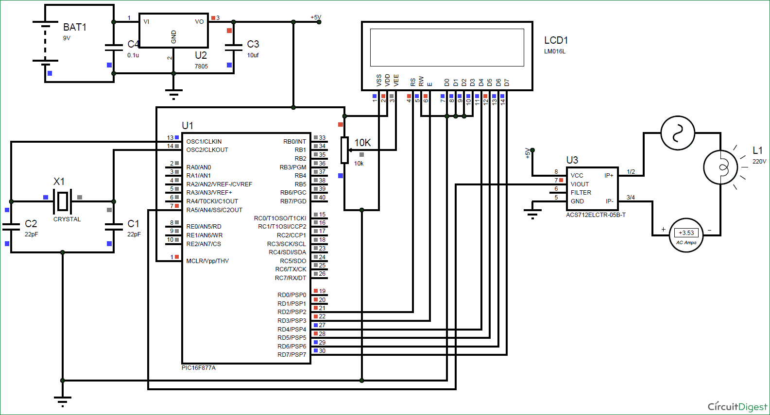
Digital Ammeter Circuit Using Pic Microcontroller And Acs712

Ammeter Design
Lesson Explainer Ammeters Nagwa

Question Identifying The Connection Of Ammeters In Circuits Nagwa

Digital Multimeter Circuit Using Icl7107

Circuit Diagram Of Thermocouple Type Ac Ammeter Jpg

Solved 20 In The Circuit Diagram Shown Below Ammeter A1 Chegg Com

Digital Panel Ammeter Wiring Diagram

A Draw Ammeter Symbol On This Circuit Diagram Where It Would Measure The Cur Through Electric Motor Teachernotes4u

Electrical Meters
