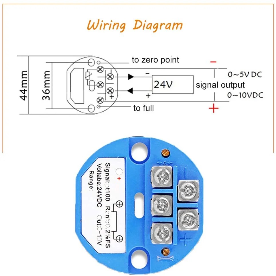
In the industrial automation world, understanding a Pt100 Temperature Transmitter Wiring Diagram is an essential skill. These diagrams can give you a clear understanding of how a temperature transmitter system works and what components are necessary for it to function correctly. With the right tools, you can create a reliable and secure temperature monitoring system that will help protect your industrial equipment and keep it running efficiently.
Pt100 temperature transmitters provide precise and reliable measurements of temperatures in extremely harsh environments. They are commonly used in hazardous areas, such as chemical plants and oil platforms, and are capable of measuring temperatures from -200°C to +600°C. A Pt100 temperature transmitter typically consists of four wires: power, signal, ground, and shield. Understanding how to wire these components correctly is key to proper operation.
The most important part of a Pt100 Temperature Transmitter Wiring Diagram is the connection between the temperature transmitter and the incoming electrical power source. This is usually done through a double-pole switch, where one pole is connected to the power source and the other to the temperature transmitter. The two poles then connect to the four wires of the temperature transmitter. The power wire and signal wire form the circuit, while the ground and shield wires act as protection against electrical interference.
The next step is to connect the temperature transmitter to a controller or other measuring device. This can either be done directly, with the temperature transmitter connected directly to the controller, or through a transmission line. When connecting directly to a controller, the temperature transmitter must be wired to the following four pins: V+, GND, S, and R/S. When using a transmission line, the temperature transmitter must be wired to the first three pins and a fourth pin for the return-signal connection.
Finally, the temperature transmitter should be tested to ensure that it is operating properly. A Pt100 temperature transmitter is calibrated to a certain range of temperatures before it is installed, so testing should include a temperature change within this range. If the temperature transmitter is found to be inaccurate, it should be recalibrated or replaced.
With the right wiring diagram and a little bit of knowledge, you can easily create a reliable and secure temperature monitoring system using a Pt100 temperature transmitter. Understanding the components of a temperature transmitter system, connecting them correctly, and conducting frequent tests will ensure that your system functions properly and safely.

China 2 Wire 4 20ma Pt100 Temperature Transmitter Output

How Does A Pt100 Sensor Work Epic Sensors
Tp3231 Evaluation Unit For Pt100 Pt1000 Temperature Sensors Ifm
Temperature Transmitter Txrail 4 20 Ma

Pt100 In 2 3 Or 4 Wire Connection Wika Blog

Rtd Temperature Measurement With Usb Data Acquisition Hardware Software

Pt100 In 2 3 Or 4 Wire Connection Wika Blog
Series 442 Installation And Operating Instructions
Temperature Sensor Instruction Manual

Pt100 Rtd Temperature Sensor What Is And Easybom

Pt100 Rtd Thermal Sensor Pyr0 Piezo
Temperature Sensor Pt100 4wire Circuitlab

Pt100 Rtd Temperature Sensor What Is And Easybom

4 Wire Rtd Temperature Sensor Resistance Detector
2 3 4 Wire Rdt Pt100 To Pt1000 Temperature Measurement

Pt100 Rtd Temperature Sensor Transmitter Module 4ma To 20ma 50 150 Celsius Degree 0 2 Fs Isolated Pack Of Canada

The Improved Temperature Measurement Circuit Scientific Diagram

Rtd Amplifier Circuit Measuring Rtds Connecting To Analog Digital Converter A D

2 3 And 4 Wire Rtds What Is The Difference

Technetea Temperature Measurement With A Pt100 Or Pt1000 Sensor
