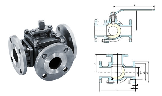
As industries and businesses expand, the need for reliable and efficient tools to regulate the flow of liquid and gas increases. One of the most widely used tools in this regard is the Three Way Valve Diagram. The valve diagram is a complex network of valves that are connected in various configurations, allowing for the accurate control of fluid motion.
The three-way valve is a characterized by its ability to open, close and control the flow of liquids and gases. It operates by controlling the pressure inside the system and regulates the flow of the liquid or gas. This type of valve has been widely used in industrial and commercial applications, such as in oil and gas pipelines, chemical production, pharmaceuticals, and other process industry applications.
The Three Way Valve Diagram consists of several components, including the main valve, the bypass valve, the drain valve, and the vent valve. Each of these valves has the ability to regulate the flow of the fluid and can be used to create the desired flow pattern. The valve diagram also includes other control systems such as pressure switches, positioners and actuators, which allow for further control over the flow of the liquid or gas.
The Three Way Valve Diagram is an integral part of many industrial and commercial processes, as it allows for precise control of the flow of liquids and gases. It is essential for ensuring the efficient and effective operation of factories, plants, and other production facilities. By understanding and correctly using the valve diagram, businesses can ensure the reliability and efficiency of their operations.
P Ids Piping Instrumentation Diagrams And Id Valve Symbol Library

3 Way Direct Acting Solenoid Valve

Three Way Control Valve Siemens Vxf 42 15 4 Bola Systems

Mark One Three Way Control Valve

Valve Symbols In Process And Instrumentation Diagrams Tameson Com
Actuated Globe Valves

3 Way 1 4 In Fnpt Vc Valve Vcznd7100 U

Three Way Poppet Valve

Tg Series Three Way Globe Control Valves Kg Equipments

Three Way Ball Valve Flow Patterns Ism

Learn More About Hvac Three Way Valves Controls

Three Way Ball Valve Has Six Structural Characteristics Xinhai

T Port And L 3 Way Ball Valves Differences Covna
New Swagelok 8xl Series 3 Way Ball Valve

3 Way Globe Type Control Valve Supplier Thinktank

Electric Converging 3 Way Control Valve Pneumatic Pressure Flow Temperature Water Manufacturer

Three Way Clamp And Weld Valves

Schematic Diagram Of 3 Way Control Valve For Precision Temperature Scientific

3 Way Ball Valves Multi Directional Flow 7g Series On Hoke Inc

