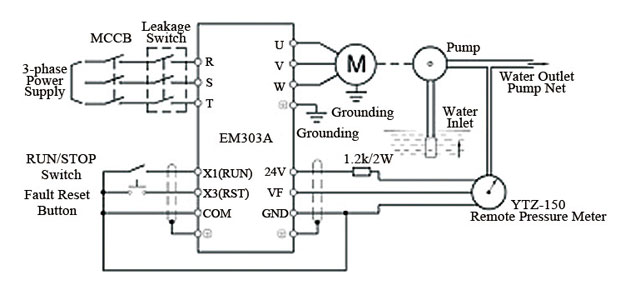
For many industrial applications, the three wire control circuit diagram and VFD (Variable Frequency Drive) are essential components. This combination is designed to provide an efficient and safe means of controlling and monitoring motor speed, torque, and other parameters. With its versatility and ease of use, the three wire control circuit diagram and VFD are a popular choice for automation systems.
The three wire control circuit diagram is composed of two parts: the load side, which is connected to the motor, and the power side, which is connected to the VFD. The diagram consists of three wires – two of which are connected to the VFD and one connected to the motor. The VFD is responsible for adjusting the frequency of the motor to adjust its speed.
The two wires connected to the VFD are responsible for regulating the voltage, while the third wire passes the current from the VFD to the motor. This allows for precise control over the speed of the motor and helps reduce energy loss. The VFD also provides a safety feature by automatically shutting down the motor if it reaches an unsafe level of speed.
The three wire control circuit diagram and VFD are an essential part of any automation system. Their simple design and easy operation make them a popular choice for industrial applications. With their versatile and reliable performance, these components can be used to make sure that your motors are running efficiently and safely.

Sd Control Basics Vfd Or Triac For Ac Induction Motors

How To Wire A Vfd Motor Three Phase And Single Wiring Electrical Automation Plc Programming Scada Pid Control System

File Vfd Wiring Diagram Jpg Probotix Wiki

Vfds For Single Phase Applications Keb

Ac Motor Control Circuits Worksheet Electric

Variable Frequency Drive For Constant Pressure Water Supply

Controlling 3 Phase Induction Motor Using Vfd And Plc

How To Make A 3 Phase Vfd Circuit Homemade Projects

Controlling 3 Phase Induction Motor Using Vfd And Plc

Controlling Vfds With Manual Inputs Technical Articles

Three Wire Control Circuit

Forward And Reverse Vfd Wiring For Lift Application Electric Motors Generators Engineering Eng Tips

Plc Drive Vfd Control Automationprimer

Controlling Vfds With Manual Inputs Technical Articles

Delta Vfd B Series Standard Wiring Diagram

Motor Control Design Automationprimer

Saftronics S10 Basic Wiring Diagram

Vfd Motor Control With Fwd Rev And Limit Switches Electric Motors Generators Engineering Eng Tips

Mastering Motor Control Center Mcc Wiring Diagrams And Equipment From Zero To Hero Eep

Variable Frequency Drives Explained Vfd Basics
