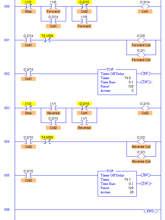
Automatic Forward and Reverse Control Circuit PDF
An automatic forward and reverse control circuit is a type of electrical circuit that allows a motor to be operated in either the forward or reverse direction. This type of circuit is often used in applications where the direction of rotation of the motor needs to be changed frequently, such as in conveyor belts, elevators, and other industrial machinery.
The basic components of an automatic forward and reverse control circuit include a motor, a switch, and a relay. The motor is the device that converts electrical energy into mechanical energy. The switch is used to control the flow of electricity to the motor, and the relay is used to change the direction of rotation of the motor.
When the switch is in the forward position, electricity flows through the relay and causes the motor to rotate in the forward direction. When the switch is in the reverse position, electricity flows through the relay in the opposite direction, causing the motor to rotate in the reverse direction.
Automatic forward and reverse control circuits can be used in a variety of applications, including:
- Conveyor belts
- Elevators
- Industrial machinery
- Robotics
- Other applications where the direction of rotation of a motor needs to be changed frequently
If you are looking for a way to control the direction of rotation of a motor, an automatic forward and reverse control circuit is a great option. This type of circuit is easy to install and maintain, and it can be used in a variety of applications.
Here is a diagram of an automatic forward and reverse control circuit:

In this circuit, the switch is connected to the motor in series with the relay. When the switch is in the forward position, electricity flows through the relay and causes the motor to rotate in the forward direction. When the switch is in the reverse position, electricity flows through the relay in the opposite direction, causing the motor to rotate in the reverse direction.
The relay is a type of switch that is controlled by an electromagnet. When the electromagnet is energized, it closes the contacts of the relay, allowing electricity to flow through the relay. When the electromagnet is de-energized, the contacts of the relay open, preventing electricity from flowing through the relay.
The electromagnet in the relay is connected to the switch. When the switch is in the forward position, electricity flows through the switch and energizes the electromagnet. This causes the contacts of the relay to close, allowing electricity to flow through the relay and the motor. When the switch is in the reverse position, electricity flows through the switch in the opposite direction, de-energizing the electromagnet. This causes the contacts of the relay to open, preventing electricity from flowing through the relay and the motor.
Automatic forward and reverse control circuits are a simple and effective way to control the direction of rotation of a motor. This type of circuit is easy to install and maintain, and it can be used in a variety of applications.

Motor Control Circuits Ladder Logic Electronics Textbook

Ta2042f Datasheet Toshiba Semiconductor Datasheetspdf Com

Index 224 Control Circuit Diagram Seekic Com
The Circuit Diagram For Dc Motor Forward And Reverse Direction Scientific

3 Phase Motor Control Using Plc Ladder Logic Tutorials Point

Motor Control Circuits Ladder Logic Electronics Textbook

Plc Program To Control Motor In Forward And Reverse Direction Sanfoundry
Ex3 Forward Reverse Motor Operation

Motor Circuits And Control Applied Electricity

Forward Reverse Control

Plc Programming Example For Motor Forward And Reverse Control

Auto Transformer Starter Your Electrical Guide

3 Phase Forward Reverse Switch Wiring Diagram Earth Bondhon

Plc Implementation Of Forward Reverse Motor Circuit With Interlocking

How Does One Connect A Dol Forward Reverse Motor Circuit To Prevent Both Contactors From Being On At The Same Time Quora

On Off Electric Motor Control Circuits Discrete System Elements Automation Textbook

Automatic Reversing Circuit Mk Iv Basic Diagram Seekic Com

Sequential Timer For Dc Motor Control Full Electronics Project
