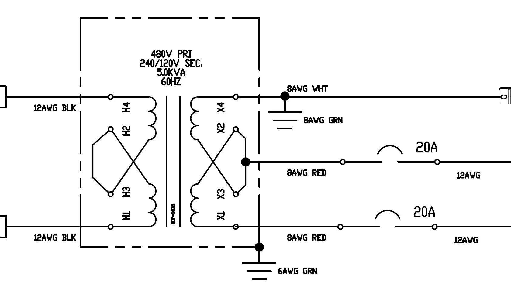
Transformers are a crucial component of many electrical systems, enabling the safe and efficient transfer of power between different voltages. A 480 to 120 volt transformer wiring diagram is an essential tool for any technician or electrician who needs to be able to quickly and confidently rewire or install a transformer. In this article, we’ll walk through the basics of how to read a 480 to 120 volt transformer wiring diagram, so that you can safely and effectively complete your own installations.
First, it’s important to understand the overall structure of a transformer wiring diagram. These diagrams show all of the elements of the transformer, including the transformer core, windings, terminals, and so on. The diagram also shows the various connections between each element. All of these connections must be completed correctly in order for the transformer to work properly.
When looking at a wiring diagram, it helps to start by understanding the different components of the transformer. The transformer core is typically the central element, and the windings are located around the core. Each winding will have two terminals connected to it, one for the input voltage and one for the output voltage. There may also be additional terminals for neutral, ground, and other connections.
The windings also connect to the terminals in a specific order. This order is usually indicated by a series of arrows pointing from one terminal to another. In the case of a 480 to 120 volt transformer, the arrows will point from the primary input voltage (480) to the secondary output voltage (120). Understanding the order of the terminals is essential when rewiring or installing a transformer.
Once you understand the overall structure of the diagram, the next step is to identify each of the specific connections. This will involve tracing the arrows from one terminal to the next, and making sure that all connections are completed correctly. It’s also important to check that all of the terminals are labeled correctly, as it’s easy to make mistakes when connecting terminals.
Finally, it’s important to check the diagram for any errors that could affect the performance of the transformer. This could include incorrect connections, missing connections, or damaged components. Once all of these issues have been addressed, the last step is to test the transformer to ensure that it operates correctly and safely.
A 480 to 120 volt transformer wiring diagram is an invaluable resource for any technician or electrician. By following the steps outlined above, you can quickly and accurately rewire or install a transformer, ensuring that it operates safely and efficiently. With a bit of practice, you can soon become an expert in reading and understanding these diagrams.
Single Phase Transformer Connections The Electricity Forum
Control Power And Encapsulated Transformers 600v Class Small

Hs14f10bs 10kva 208 240 415 480 Primary 120 240v Secondary Single Phase Transformer

Power Distribution Configurations With Three 3ph Lines
Control Wiring Diagrams

Sizing Conductors Part Vi Electrical Contractor Magazine

Grounding For Control Transformers Technical Articles

Using Potential Transformers Continental Control Systems Llc

5 Kva Transformer Primary 240 X 480 Secondary 120 Federal Pacific Se2t5f

750 Kva Transformer Primary 480 Secondary 208y 120 Jefferson 423 9364 000

3 Phase Tb Jpg

Solved Chapter 2 Problem 31p Solution Fitzgerald Kingsley S Electric Machinery 7th Edition Chegg Com

Open Coil Machine Tool Control Transformer

Grounding For Control Transformers Technical Articles

Control Transformers Power Voltage Stepdown Converters

Single Phase Transformers Connected In A Wye Installation

Transformer Installation Made Easy Sort Of Ec M

240vac And 480vac Step Down To 120vac Or Control Transformers
