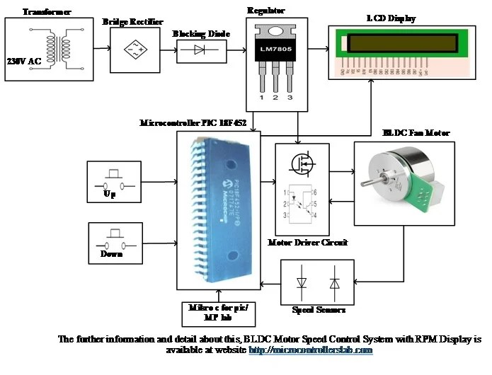
The world of robotics and machine automation is an exciting and ever-expanding realm. As technology continues to advance, many applications are leveraging the power of BLDC motor circuits to maximize efficiency and accuracy. But what exactly is a BLDC motor circuit and how does it work?
A BLDC motor circuit is a type of brushless DC motor system that uses electronic commutation to control the speed and torque of the motor. This allows the motor to operate efficiently and with higher torque than other types of DC motors. The motor consists of three main parts: the stator, rotor, and Hall sensor. The stator is a stationary part that consists of multiple electromagnets, while the rotor is a rotating part with permanent magnets attached. The Hall sensor is responsible for sensing the rotational position of the rotor in order to send the appropriate electrical signals to the motor for proper commutation.
To understand how a BLDC motor works, it’s important to understand the fundamentals of its operation. Each time a current is applied to one of the stator coils, a magnetic field is generated. This field interacts with the magnets on the rotor and causes it to rotate. As the rotor rotates, the Hall sensor detects the position of the rotor and sends a signal to the motor controller. The motor controller then sends the appropriate electrical signals to the motor in order to properly commutate the current.
As technology continues to improve, BLDC motor circuits are becoming increasingly popular in industrial applications, robotics, and other automation tasks. To ensure proper performance, it’s essential that you have a clear understanding of the BLDC motor circuit diagram.
The BLDC motor circuit diagram consists of several key components including the motor, the Hall sensor, the motor controller, the power supply, and the connections between them. Each component is essential for the motor to operate correctly. The motor controller is responsible for providing the necessary electrical signals to the motor for proper commutation. The Hall sensor is responsible for detecting the rotor position and sending this information to the motor controller. The power supply is also an important component, providing the necessary voltage and current to operate the motor.
For a better understanding of the BLDC motor circuit diagram, let’s take a look at a step-by-step guide. First, the motor must be connected to the motor controller, with the power supply connected to the controller as well. Then, the Hall sensor should be connected to the motor controller, with the appropriate electrical signals sent to the motor. Finally, the connections between the power supply and the motor must be properly wired for the motor to operate correctly.
BLDC motor circuits are an exciting technology that is finding more and more applications in robotics and automation. By understanding the BLDC motor circuit diagram and its components, you will be able to maximize the efficiency of your motors in any application.

3 Phase Brushless Dc Motor Control With Hall Sensors Industry Articles

Bldc Motor Control Power Electronics And Drives Pantech Prolabs India Pvt Ltd

Control Engineering Understanding The Effect Of Pwm When Controlling A Brushless Dc Motor

A2212 Brushless Motor Pinout Wiring Features Specs Datasheet

Bldc Motor And Dc Brushed Driver Electronics Lab Com
Control Bldc Motor Sd Using Pid Controller

Schematic Representation Of Sensorless Bldc Motor Control Scientific Diagram

Brushless Dc Motors Bldc What Are They How Do Work

Bldc Brushless Dc Motor Driver Circuit Using 555 Ic

What Is Brushless Dc Motor Bldc And How To Control With Arduino

Discrete Time Brushless Dc Motor Cur Pi Controller With Pulse Width Modulation Generation Simulink
Bldc Motor Control Schematic Without Esc Or Ic Electronics Forums

Sensorless Bldc Motor Driver Circuit Homemade Projects

Bldc Motor Sd Control With Rpm Display System

Bldc Brushless Dc Motor Driver Circuit Using 555 Ic

Brushless Dc Motor Driver Bldc Full Diy Project

How To Make Advanced Bldc Motor Controllers Blog Altium

How To Easily Design Sinusoidal Sensorless Control For 3 Phase Bldc Motors Technical Articles Ti E2e Support Forums

Results Page 126 About Ic 4022 Searching Circuits At Next Gr
Cur Sensing In Bldc Motor Application Note
