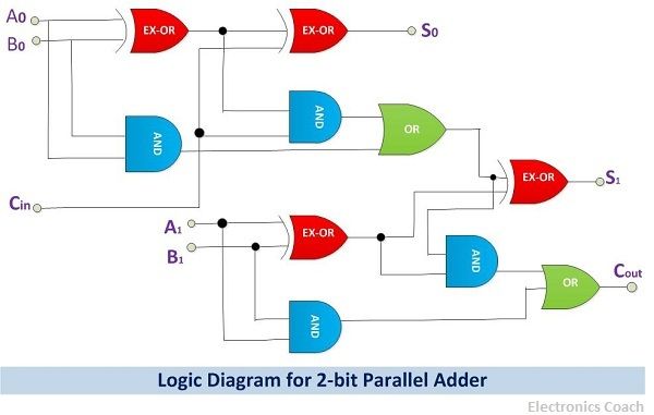
The world of computing is an incredibly complex field, and binary arithmetic is one of the fundamental concepts behind it. In this article, we'll be discussing the basics of 4-bit binary arithmetic and its associated circuit diagram.
To start off, let's have a brief look at what binary arithmetic is. Binary arithmetic refers to the use of number systems with base 2 (which uses the digits 0 and 1) for carrying out simple calculations like addition, subtraction, multiplication, and division. It is the foundation of any computer system, and understanding it is essential if one wants to gain a deeper understanding of computing.
So, how does 4-bit binary arithmetic work? A 4-bit binary arithmetic system consists of four bits, each representing a numerical value from 0 to 15, with each bit being worth twice as much as the one before it. Addition in this system can be done by connecting the four bits together in a series, known as an adder circuit. The result of the addition is then shown on the output of the circuit.
To give a more practical example, let's look at the circuit diagram of a 4-bit binary adder. In this example, we can see four inputs (A, B, C, and D) and two outputs (E and F). The inputs are where the two numbers to be added are placed, and the outputs show the sum of the two values. The circuit then uses logic to determine the sum of the two numbers based on their respective bit values.
In conclusion, 4-bit binary arithmetic is an essential concept in computer science, and understanding it is important for anyone interested in computing. The adder circuit is the foundation of 4-bit binary arithmetic, and understanding its circuit diagram is crucial for gaining an understanding of the system. We hope that this article has helped you to better understand the fundamentals of 4-bit binary arithmetic.

Combinational Circuits

Binary Adder Subtractor Javatpoint
Solved Lab 4 Binary Adder Subtractor And Multiplier Ics Chegg Com
What Is The Truth Table For A 2 Bit Adder Quora

Answers To Selected Problems In Chapter 5 Cosc3410

Half Adders And Full

4 Bit Full Adder Using Logic Gates In Proteus The Engineering Projects
1 Design Procedure Adder Subtracter Code Conversion
Solved Part A Binary Adder Subtractor 7 Marks Figure 3 Chegg Com

Coa Binary Adder Javatpoint
9 Four Bit Adder Mr Bridger S Web Page

How To Design A Four Bit Adder Subtractor Circuit Ee Vibes

Half Adder An Overview Sciencedirect Topics

How To Build Your Own Discrete 4 Bit Alu Projects
How To Make A Truth Table For 4 Bit Parallel Adder Quora

What Is Parallel Binary Adder 2 Bit And 5 Electronics Coach
Title 4 Bit Arithmetic And Logical Unit Theory

A Binary Adder Made Using And Or Array Logic

Coa Binary Adder Subtractor Javatpoint

