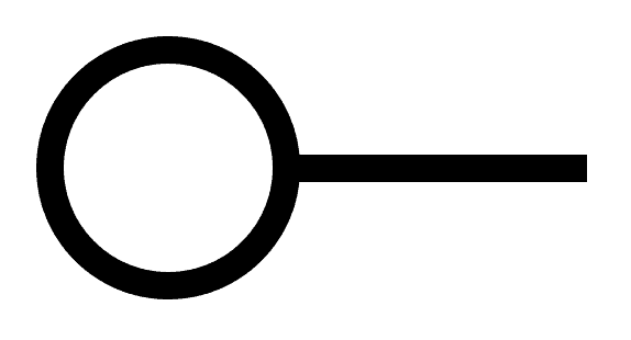
Electrical Schematic Terminal Symbols
Electrical schematic terminal symbols are used to represent the electrical connections between components in a circuit diagram. They are a vital part of any electrical schematic, as they allow engineers and technicians to quickly and easily identify the different components and their connections. There are a wide variety of electrical schematic terminal symbols, each of which represents a different type of connection. Some of the most common symbols include: *Wires:
Wires are represented by a simple line with a dot at each end. The direction of the current is indicated by an arrow. *Connectors:
Connectors are represented by a square or rectangle with two or more terminals. The terminals are typically labeled with letters or numbers. *Switches:
Switches are represented by a circle with a line through it. The line indicates the direction of the current when the switch is closed. *Relays:
Relays are represented by a square or rectangle with a coil and a set of contacts. The coil is typically labeled with the voltage and current rating, and the contacts are labeled with the type of connection (e.g., NO, NC). *Transistors:
Transistors are represented by a triangle with a line through it. The line indicates the direction of the current when the transistor is turned on. *Diodes:
Diodes are represented by a circle with a line through it. The line indicates the direction of the current when the diode is conducting. In addition to these basic symbols, there are also a number of more specialized symbols that are used to represent specific types of components or connections. For example, there are symbols for capacitors, resistors, integrated circuits, and power supplies. Electrical schematic terminal symbols are an essential part of any electrical schematic. By understanding the meaning of these symbols, you can quickly and easily identify the different components and their connections. This will make it easier for you to troubleshoot problems, design new circuits, and understand how electrical systems work. ### How to Read Electrical Schematic Terminal Symbols Reading electrical schematic terminal symbols is a relatively simple process. Once you know what the different symbols represent, you can quickly and easily identify the different components and their connections. To read an electrical schematic, start by identifying the main power source. This is usually represented by a battery or a power supply. Once you have identified the power source, you can follow the lines to find the different components in the circuit. Each component in the circuit will be represented by a different symbol. The symbol will typically include the following information: * The type of component * The direction of the current * The voltage and current rating By understanding the meaning of these symbols, you can quickly and easily identify the different components and their connections. This will make it easier for you to troubleshoot problems, design new circuits, and understand how electrical systems work. ### Conclusion Electrical schematic terminal symbols are an essential part of any electrical schematic. By understanding the meaning of these symbols, you can quickly and easily identify the different components and their connections. This will make it easier for you to troubleshoot problems, design new circuits, and understand how electrical systems work.Wiring Digrams Guide The Shortcut In Electrical Planning
Electrical Symbols And Line Diagrams One
What Is The Cb1 Symbol In This Schematic Quora

How To Read Electrical Schematics Circuit Basics

How To Read A Schematic Sparkfun Learn

A Cheat Sheet For 13 Charts To Understand Symbols In Electrical Diagram

Wiring Diagrams Explained How To Read Upmation

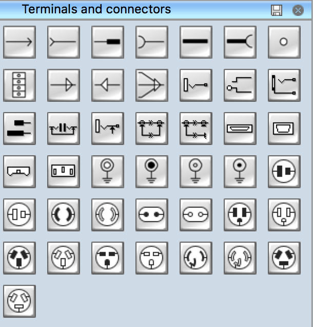
Electrical Symbols Terminals And Connectors

Electrical And Electronics Symboleanings Edrawmax Online

Electrical User S Guide Overview Of Symbol Naming Conventions

Electrical Symbols How To Read Schematics 7 Protections Blog Related Automation Plc Hmi Control Systems

Electrical Symbols Terminals And Connectors
Circuit Symbols For Wires Cables Switches Connectors Electronics Notes

How To Read A Schematic Sparkfun Learn

Electrical Schematics How To Read 1 Connectors Blog Related Automation Plc Hmi Control Systems

Electrical Symbols Symbol Reference Pumping Solutions Inc

Wiring Diagrams Explained How To Read Upmation
Terminal Block Capital Electra X Symbols

Item Designations Or Why Are Relays Called K In Schematics Circuit Breakers Q

