When it comes to electronics, understanding how to design a logic circuit from a truth table is essential. From hobbyists to professionals, knowing how to construct logic circuits is an essential skill in today's technology-driven world.
Designing logic circuits from truth tables is easier than ever thanks to the availability of powerful tools and resources. However, for those just starting out, the process can seem daunting and intimidating. That's why we're here to help!
In this article, we'll explain what a truth table is, outline the basics of constructing a logic circuit from a truth table, and provide tips and tricks to make your task simpler and easier. By the time you finish reading, you'll be on your way to designing and building complex logic circuits from truth tables like a pro.
So, let's get started!
What Is a Truth Table?
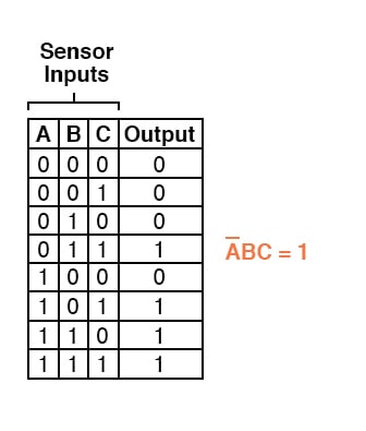
A truth table is a chart that displays all of the possible inputs and outputs for a given logic circuit or function. It is used to analyze the behavior of a logic circuit or function by enumerating all possible input combinations and their resulting output states. The rows of the table represent the individual input combinations and the columns represent the variables in the logic circuit or function.
Truth tables are helpful for visualizing the relationship between inputs and outputs, and they are invaluable when constructing complex logic circuits.
Designing a Logic Circuit from a Truth Table
Designing a logic circuit from a truth table can be broken down into four main steps:
1. Understand the function
The first step in designing a logic circuit from a truth table is to understand the desired functionality of the circuit. This means studying the truth table and determining the relationships between the inputs and outputs. It is important to note that not all logic functions can be represented in a truth table, so it is important to understand which functions can be represented this way before proceeding.
2. Construct the logic gates
Once you have understood the desired functionality of the circuit, the next step is to construct the logic gates that will be used to represent the logic function. This typically involves using Boolean algebra to reduce the truth table to a set of equations which can then be translated into the corresponding logic gates.
3. Connect the logic gates
The next step is to connect the logic gates together in order to create the desired logic circuit. This involves connecting the input and output terminals of the logic gates in order to form the appropriate connections.
4. Test the logic circuit
Finally, the last step is to test the logic circuit by simulating the various input combinations and verifying that the corresponding output states are as expected. This can be done by using a computer simulation program or simply by feeding the input signals directly into the logic circuit and observing the resulting output states.
Tips and Tricks
Designing a logic circuit from a truth table can be a challenging task, but there are a few tips and tricks that can make the process simpler and easier.
• Start by simplifying the truth table as much as possible. This will make the subsequent steps easier and more efficient.
• Use a computer simulation program to test the logic circuit. This is much faster and more accurate than manually testing each input combination.
• Remember that not all logic functions can be represented in a truth table. If the logic function is too complex, it may be necessary to use other methods such as Karnaugh maps or Boolean algebra.
Conclusion
Designing a logic circuit from a truth table is a useful skill that can be applied in many different areas of electronics. By following the steps outlined above and using the tips and tricks provided, you can easily design and build complex logic circuits with confidence. Good luck and happy building!

Solved 3 Design The Logic Circuit Corresponding To Chegg Com

Half Adder Circuit And Truth Table Electrical4u

Digital Logic Learn Sparkfun Com

Example Of A Logic Circuit And Corresponding Truth Tables The Scientific Diagram

Converting Truth Tables Into Boolean Expressions Algebra Electronics Textbook

Logic Circuits

Untitled Doent

Logic Gate Truth Tables A Complete Guide

Solved Draw The Truth Table For Circuit Below And Chegg Com

Digital Logic Learn Sparkfun Com

Karnaugh Maps Truth Tables And Boolean Expressions Mapping Electronics Textbook

Solved Activity 1 A Logic Gates Fill In The Truth Table Chegg Com

Digital Electronics Logic Gates Basics Tutorial Circuit Symbols Truth Tables

Free Truth Table To Logic Circuit Converter Software For Windows

Converting Truth Tables Into Boolean Expressions Algebra Electronics Textbook

Summary Of The Common Boolean Logic Gates With Symbols And Truth Tables Scientific Diagram

Converting Truth Tables Into Boolean Expressions Algebra Electronics Textbook

Logic Gates And Truth Tables Inst Tools
Solved Design The Logic Circuit For A Device That Has Chegg Com
