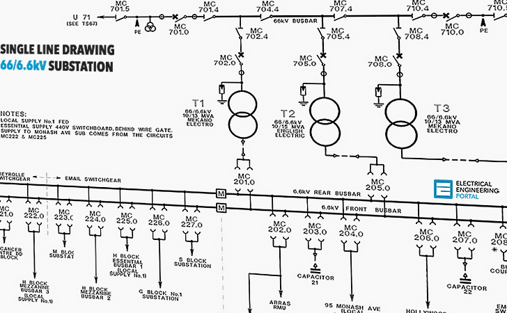
Electronic schematics are a visual representation of an electronic circuit. They show the components of the circuit, how they are connected, and the flow of electricity through the circuit. Schematics are used by engineers to design and build electronic circuits. They can also be used by hobbyists and technicians to repair and troubleshoot electronic devices.
Reading an electronic schematic can be a daunting task, but it is not as difficult as it may seem. With a little practice, you can learn to read schematics and understand how electronic circuits work.
This article will teach you the basics of reading electronic schematics. We will cover the different symbols used in schematics, how to identify the components of a circuit, and how to trace the flow of electricity through the circuit.
We will also provide some tips for troubleshooting electronic circuits. By the end of this article, you will be able to read and understand basic electronic schematics.
## Symbols Used in Electronic Schematics The first step in reading an electronic schematic is to learn the different symbols used to represent the components of a circuit. The following table lists some of the most common symbols used in schematics.
| Symbol | Component |
|---|---|

|
Resistor |

|
Capacitor |

|
Inductor |

|
Diode |

|
Transistor |
In addition to the symbols for individual components, there are also symbols for electrical connections, power sources, and ground. The following table lists some of the most common symbols used for electrical connections.


