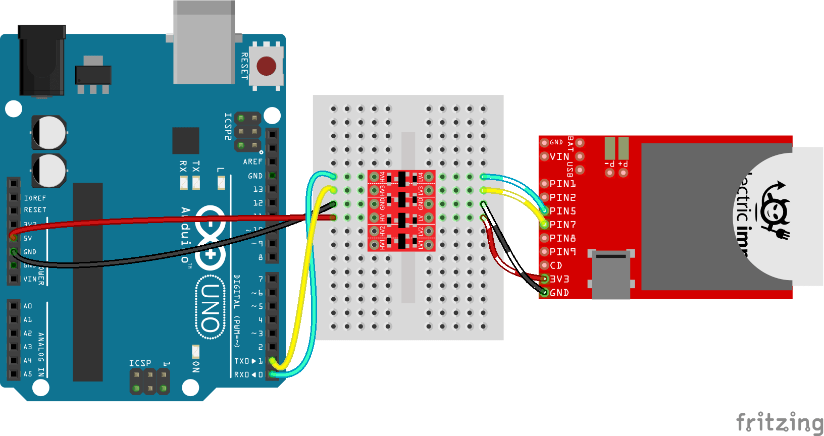
The level shifter circuit diagram is an essential tool for understanding electrical engineering. It is used to convert two different voltage levels without introducing any distortion, spikes, or surges into the resulting signal. This circuit diagram helps engineers and students alike understand how to use electronics to solve real-world problems.
At its core, a level shifter circuit diagram is a visual representation of how electronic components are connected in order to shift one voltage level to another. This could be a conversion from low voltage to high voltage, high to low, and so forth. The diagram will show the components connected together in a circuit, as well as the inputs and outputs that the components need in order to function properly.
When working with level shifter circuits, it is important to remember that there are two main types – analog and digital. Analog circuits are designed to convert voltages more quickly and with more accuracy than digital circuits. Digital circuits are designed for faster switching speeds and can handle higher frequencies and voltages.
In order to use a level shifter circuit diagram, the user needs to know what type of circuit they are working with, as well as the voltage levels they are trying to convert. Once these parameters are known, the user can begin to draw out their circuit diagram. Common components that are used in level shifter circuits include resistors, capacitors, transistors, diodes, transceivers, and optocouplers.
When drawing the circuit diagram, it is important to note how each of the components are connected. In addition, the inputs and outputs should also be labeled according to their function. A typical circuit diagram looks something like this:
Once the user has all of the components connected properly, they can then test the circuit to make sure it is functioning correctly. Before connecting components to the circuit, it is important to make sure that the voltages are correct. This is done by testing the voltages at each junction point to ensure that the correct voltage is being sent to the correct component.
Level shifter circuit diagrams are an essential tool for any student or engineer working with electronics. By understanding the basics of how these diagrams work, users can easily create a functional circuit that can be used in any number of applications. With proper testing and verification, users can trust that their circuit will function reliably and safely.
High Voltage Level Shifter Circuit Design For Efficiently Transducer Driving
Cd40109b Q1 Cmos Quad Low To High Voltage Level Shifter Datasheet Rev A

Taking It To Another Level Making 3 3v Speak With 5v Hackaday

Level Shifter Circuit Schematics A Conventional Cross Coupled Half Scientific Diagram

Bi Directional Logic Level Converter Guide Learn Sparkfun Com

A High Density Performance Low Power Level Shifter

Circuit Diagram Of The Level Shifter Scientific
I2c Level Shifter Mk2 Circuitlab

High Performance Cmos Level Up Shifter With Full Scale 1 2 V Output Voltage Sciencedirect

3 3v To 5v Logic Level Shifter Using Transistors General Electronics Arduino Forum

Bi Directional Logic Level Converter Using Mosfet

Level Shift Pwm Logic Signal 3 3v To 5v Avr Freaks

How To Level Shift Signals For Dc Coupled Amplifiers Filters
Logic Level Shifter 4 Channel Bidirectional

Digital Voltage Level Shifter With An Analog Twist

Level Shift Allows Cfa Amplifier To Swing Ground On A Single Supply Analog Devices

Mosfet Level Shift Electronics Information From Penguintutor

The Circuit Diagram Of Level Shifter Scientific
Level Shifter 12v 3 3v Circuitlab

How To Level Shift 1 Wire Systems
