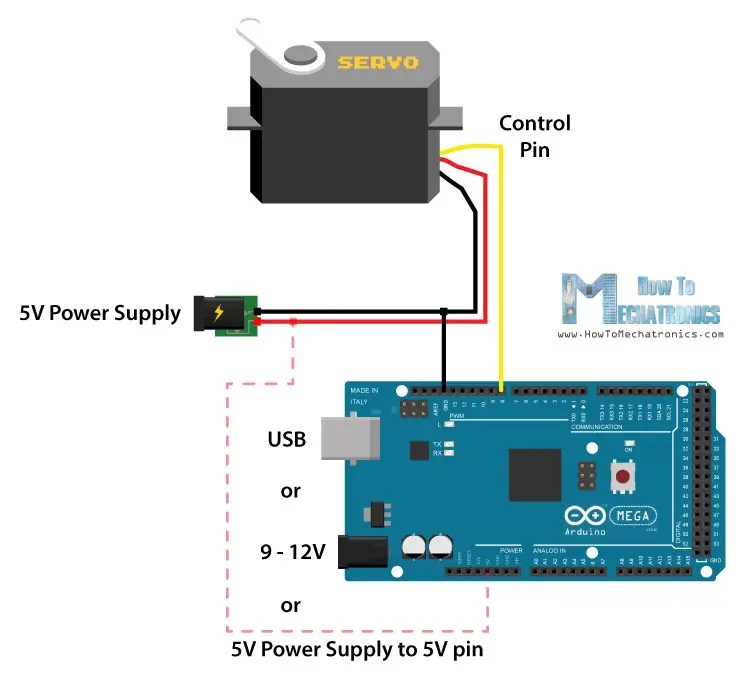
Servo Motor Circuit Diagrams: Understanding How They Work and What They Do
Understanding servo motors is an essential part of any robotics or automated systems design. A servo motor circuit diagram provides the clearest insight into how these motors work and how they are used in a variety of applications. This article will explain what servo motors are, how they work, and why they are important for robotics applications.
Servo motors are small, electric motors that are designed to be used in robotics and automated systems. They are capable of providing precise control over the position, speed, and torque of an actuation system or robotic arm. The best way to understand how servo motors work is by looking at the servo motor circuit diagram.
A servo motor circuit diagram shows you how the various components of a servo motor are connected. It includes all of the electrical connections between the motor, its power source, and the controller. Additionally, it provides a visual representation of the mechanical elements, such as the gear box, encoder, and other parts that allow the motor to move.
When a signal is sent to the servo motor, it will cause the motor to turn in one direction or the other. The motor has two main components, the rotor and the stator. The rotor is the part that turns when the motor is activated and the stator is the stationary portion. The stator contains an encoder that enables the motor to be accurately positioned and the rotor contains the gearbox which allows the motor to be able to turn at different speeds.
When a signal is sent to the motor, it causes the rotor to rotate, causing the gearbox to turn the motor at the desired speed. The encoder will then measure the position of the motor and send a signal back to the controller. This signal is then used to control the motor’s movement.
Servo motors can be used in a wide variety of applications, such as robotics, surgical instruments, prosthetics, and automated manufacturing processes. They are also used in aeronautics and aerospace, as well as industrial automation. Understanding the servo motor circuit diagram is essential to understanding how the motor works and how it can be used in a variety of applications.
Servo motors are useful in many applications, but they require careful consideration when designing and building a robotic system. Knowing how the various components are connected and how the motor works is important so that you can properly integrate the motor into your project. Studying and understanding the servo motor circuit diagram is an important step in designing and building a reliable, functional robotic system.

Servo Motor Sg 90 Basics Pinout Wire Description Datasheet And Working
.png?strip=all)
Et E 08a Ac Servo Drives

Servo Motor Driver Circuit

How Servo Motor Works Interface It With Arduino Last Minute Engineers
Servo Motor System Controller Under Repository Circuits 22818 Next Gr

Servo Motor Control With An Arduino Projects

Servo Motor Control With An Arduino Projects

Ac Servo Motor Controller Circuit Diagram

How To Control Servo Motors With Arduino 3 Examples

Joystick Controller For Servo Motor Gadgetronicx

Picture Transpa Collection Of Free Circuit Servo Driver Schematic Png Image With No Background Pngkey Com

Schematic Diagram Of Mini Servo Motor With Arduino Mega In Main Circuit Scientific

Servo Motor Control Schematic Pyroelectro News Projects Tutorials

How To Control Servo Motors With Arduino Complete Guide

How To Control Servo Motors With Arduino Complete Guide

Lab 21 Servo Motor Control Embedded

Arduino Servo Control Schematic Pyroelectro News Projects Tutorials

Servo Motor Driver Circuit

How To Run A Servo Motor Using Ic 555 Homemade Circuit Projects
