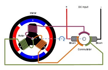
Are you looking for a wiring diagram for a single phase brushless generator? You’ve come to the right place! In this article, we’ll provide an easy-to-understand overview of the wiring and connections required to properly power up a single phase brushless generator.
Single phase brushless generators are one of the most efficient ways to generate power from small to large scale applications. They are used in a variety of applications such as powering industrial machinery, electrical equipment, and even residential homes. The brushless design of these generators makes them reliable and provides a steady, consistent output of power.
If you’re looking to install or repair a single phase brushless generator, you’ll need to understand how it’s wired. Before we get into the specifics of the wiring, let’s review the components that make up the generator. A single phase brushless generator is composed of three main parts: the stator, the rotor, and the controller.
The stator is the stationary part of the generator which houses the winding coils that generate the power. The rotor is the part that rotates inside the stator, driven by an external power source. The controller is the part that controls the speed and output of the generator.
Now that you know the basic parts of the generator, let’s look at the wiring diagram. First, you’ll need to connect the stator and the rotor. To do this, you’ll need to run a line from the stator to the rotor. Next, you’ll need to connect the controller to the stator and the rotor. This can be done with either a three-wire connection or a four-wire connection, depending on the type of generator you’re using.
Finally, you’ll need to connect the generator to the power source. Depending on the type of generator, this could be done using either a direct current (DC) connection or an alternating current (AC) connection. DC connections require two wires while AC connections require three wires.
Wiring a single phase brushless generator is not a difficult process, but it’s important to make sure all the connections are correct and secure before turning on the generator. If you’re not sure how to properly wire a single phase brushless generator, you should consult a professional who has experience with this type of generator.
We hope this article has provided you with a better understanding of the wiring and connections needed to operate a single phase brushless generator. With this knowledge, you can now safely operate your generator and start experiencing the benefits of clean, efficient power.

China Single Phase Brushless Generator Circuit Diagram Automatic Voltage Regulator Avr As480 Photos Pictures Made In Com

Connection Diagram Of The Single Phase Induction Generator Scientific
Mastervolt Single Phase Ac Alternators

China Single Phase Brushless Generator Circuit Diagram Automatic Voltage Regulator Avr As480 Photos Pictures Made In Com

Self Excited Single Phase Induction Generator With Excitation Capacitor Scientific Diagram

How Does Brushless Alternator Works With Diagram

China Single Phase Brushless Type Circuit Diagram Avr Ea05a Permanent Magnet Generator Automatic Voltage Regulator Ilizer For Kutai

Single Phase Brushless Generator Circuit Diagram Automatic Voltage Regulator Avr As480 China Made In Com

Brushless Alternator Marine Inbox

Alternator Leroy Somer Lsa 42 3 S5 Single Phase Dedicated 50 Hz
Agn 102 Markon Alternators

Energies Free Full Text Use Of Discharge Resistor To Improve Transient De Excitation In Brushless Synchronous Machines Html
Sensored Single Phase Bldc Motor Driver Using Pic16f1613

Brushless Vs Brushed Dc Motors When And Why To Choose One Over The Other Article Mps
How Is Excitation Controlled In A 3 Phase Brushless Ac Generator With Three Sensing Avr Quora

Single Phase Alternator K100 Series Nuova Saccardo Motori Brushless 2 Pole
Training Module For Kirloskar Shakti A C Generator 2 Jun 152 1511

Connection Diagram Of The Single Phase Induction Generator Scientific
