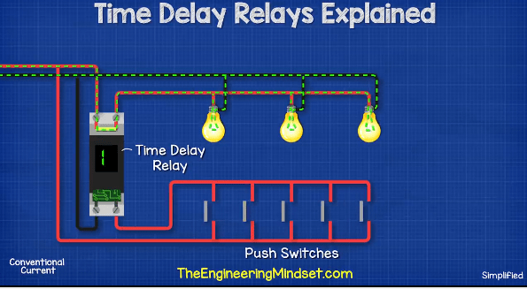
As anyone who works with electrical circuits knows, the connection between a timer relay and the power source is essential to ensure consistent, reliable operation of devices in the circuit. A timer relay connection diagram outlines the connections provided between a timer relay, its power source, and the rest of the circuit. Knowing how to properly connect these components can be vital for avoiding costly mistakes and damaging equipment.
Timer relays are an important part of many industrial and commercial operations, as they provide a means of automating processes and controlling them in precise ways. By ensuring that the timer relay is connected correctly and that the timing sequence is set correctly, businesses can ensure that their operations run smoothly and efficiently.
Different types of timer relays require different kinds of diagrams for connecting them to the power source, but the principles remain the same. Connecting the timer relay to a power source is an important first step, as it allows the timer relay to operate and signal to other components of the circuit. Once the timer relay is connected to a power source, other components of the circuit will be connected to the timer relay in order to receive signals from it.
It is also important to understand the various types of wiring that can be used when connecting a timer relay to the power source. Some timer relays may require direct wiring, while others may require more complex wiring methods such as using a timer relay switch. Depending on the type of timer relay being used, the wiring requirements may vary significantly.
Once the timer relay is connected to the power source, the next step is to connect the timer relay to the other components of the circuit. This will depend on what type of timer relay is being used and what components it is connecting to. For example, if the timer relay is connecting to a motor, then a specific type of wiring will need to be used. It is also important to ensure that all components are correctly wired according to the timer relay connection diagram.
When connecting the timer relay to the power source, it is important to ensure that the voltage ratings for the timer relay and the power source match. If the voltage ratings do not match, then the timer relay will not work correctly and can potentially cause damage to the circuit. Additionally, all wiring should be checked for shorts, ensuring that no loose wires are present.
In conclusion, it is important to understand all of the necessary information required to properly connect a timer relay to the power source. A timer relay connection diagram should be consulted in order to ensure that the timer relay is connected correctly and that all components are wired in the correct manner. Knowing how to properly connect the timer relay can save time and money, and potentially even lives.

Ah3 N 3a On Delay Time Super Relay 220v Inductive Proximity Sensor Photoelectric Capacity Solid State Pcb Timer

Time Relay Delay Manufacturer From China Alion

Programmable Timer Relay 8 Input Output 12v 24v Dc Ato Com

Nte8 Time Delay Relay Chint
How Do I Glow Plug Timer Relay Land Rover Uk Forums

An Automatic Cw T R System For Vintage Stations Ac Wiring
Electronic Time Relays

Thermostat Delay Relay Timer Circuit Homemade Projects
Eee Tutors 8 Pin Timer Relay Wiring Connection Diagram Controlling Facebook By 3 Phase Motor Series Provide

Digital Timer Relay 8 Pin 12v 24v 220v Ato Com

Time Delay Relays Explained The Engineering Mindset

Arduino Relay Timer Circuit With Uno

Time Relay Delay Manufacturer From China Alion

Timing Relay Control Relays And Timers

4541 Timer Relay Circuit 0 3 Second To 10 Hours

St3pf Time Delay Relay Electronic General Purpose Timer Inductive Proximity Sensor Photoelectric Capacity Solid State Pcb

Time Delay Relay Tdr 120vac 24vdc

Multi Functional Time Relay 10 Programs 30 Hours 12vac 240vac Dc Vteke Electrical Manufacturers

Digital Timer Relay 8 Pin 24v Dc 110 240v Ac Ato Com

