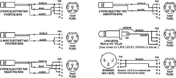
What is a Turner Mic Wiring Diagram?
If you are a sound engineer or technician, then you must have heard about the Turner mic wiring diagram. This diagram is used to build the wiring for a microphone system and is essential for setting up a professional microphone recording setup.
The Turner mic wiring diagram is used to wire different types of microphones and is designed to help professionals make sure they have the right connections in place. The diagram provides a clear visual representation of how the wiring should be done. It also contains detailed instructions on what type of hardware is needed for each connection.
In addition to providing a beneficial diagram, the Turner mic wiring diagram has become popular in the audio engineering community because it can help reduce noise levels in recording setups. This is especially useful for low-budget studios and live sound engineers who need to limit their noise levels.
When creating a Turner mic wiring diagram, there are a few things to consider. First and foremost, all the components must be correctly labeled and connected. Second, the wiring colors should correspond to the colors of the components in order to make it easy to identify and connect each component. Third, the wiring should be neat and organized so that it doesn’t create additional noise or confusion. Finally, the wiring should be adequately secured so that it won’t come loose or disconnect during use.
Using the Turner mic wiring diagram can greatly reduce problems with noise, feedback, and interference in your recording setup. As such, it is an essential tool for anyone looking to create a professional sound recording setup. By following the instructions outlined in the diagram, you can ensure that your equipment is properly wired and connected. This will help to maximize the quality of your recordings and reduce the amount of time spent troubleshooting.
Turner 3 Instructions And Circuit Diagram

Date

How To Fix Cb Microphone Wiring With Diagram And Color Code
Microphone Wiring Diagrams

Mike Wiring Guide

Mike Wiring Guide

President Richard

Shure 522 Base Station Mic Wiring The Cb Radio Talk Forum

Yaesu Ft 2400 Mic Connector Jpg

Woody S Turner Microphone Page

Vintage Turner 454c Ssb Microphone 169036258

Microphone Wiring Diagram

Copper Talk Turner M 2 U Wiring For 4 Pin Cobra Uniden

Turner Co 5780 Amplified Parts
Microphone Wiring Diagrams

Date
Eham Net

Vhf Transmitter 5 Pin Input Jack Wiring

Date
